
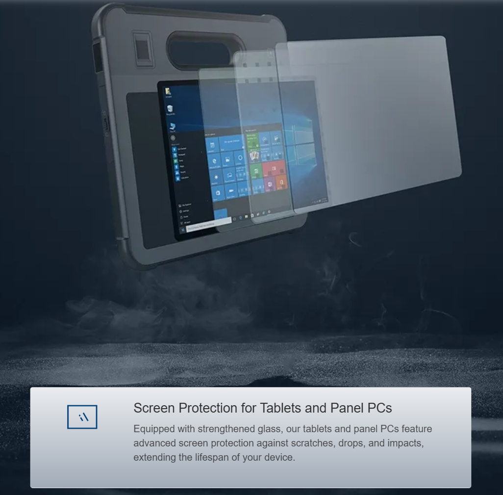
Comparative insight begins with clear criteria: performance targets, ESD isolation, and shielding effectiveness must be weighed together rather than in sequence. Please note that industry deployments—from shore-side SCADA racks to forward operating kits—have different tolerances for electromagnetic interference and mechanical stress. A pragmatic comparison clarifies whether to choose a purpose-built rugged computer platform with integrated shielding or a custom board inside a tailored enclosure. Standards such as MIL-STD-810G and IEC 61000-4-2 provide the real-world anchor for these choices, and they guide acceptable levels for ESD isolation and EMC performance.
Design trade-offs: integrated shielding versus modular guardrails
High-performance embedded boards demand open layouts for cooling and signal routing, yet shielding and ESD isolation require close control of return paths and enclosure continuity. A tightly integrated shield (a Faraday cage style enclosure) offers predictable EMI suppression and straightforward ESD discharge paths, while modular guardrails—removable covers, EMI gaskets, and isolated card guides—improve serviceability. Considerations include PCB ground plane strategy, shield seam resistance, and connector bonding. In practice, an integrated shield typically yields better dB attenuation across broad bands; modular systems win on repairability.
Thermal and mechanical considerations that affect shielding
Thermal management and mechanical protection are interdependent with EMI strategies. Heat spreaders, thermal vias, and conductive TIMs may need to cross shield boundaries; if not carefully engineered, they become unintended ESD conduction paths. Shock and vibration damping—using elastomer mounts or bonded standoffs—must preserve electrical continuity for the shield while isolating the PCB from mechanical loads. Conformal coating offers additional protection for corrosion and air-borne contaminants, but excessive coating on connector interfaces can impede contact and bonding for shield attachments.
Comparative deployment scenarios and product fit
Compare three common scenarios to see how priorities shift: industrial HMI installs favor serviceability and predictable EMI control; field measurement rigs prioritize lightweight assemblies and robust ESD isolation; military applications often demand the highest combined levels of shielding and MIL-standard shock/vibration resistance. For operator-facing systems where touch and mobility matter, a purpose-built rugged laptop tablet can integrate sealing, display EMI suppression, and ESD wrist-strap interfaces into a single verified package—reducing the integration effort on the embedded board side. Each scenario maps to different trade-offs in mass, thermal headroom, and repair cycles.
Common mistakes and practical alternatives
The following issues recur in project reviews; avoiding them shortens qualification time and reduces field failures—
– Over-shielding vents without conductive gasketing, which blocks airflow but leaves seams that leak EMI. Use vented conductive screens or staggered labyrinths instead.
– Grounding only at a single point and assuming PCB traces will carry discharge safely. Implement multi-point bonding with low-impedance straps and consider isolated chassis grounds where appropriate.
– Relying solely on conformal coating for ESD protection. Combine coating with physical standoffs and targeted shielding at high-risk connectors.
Credibility and field evidence
Field-tested practice matters: MIL-STD-810G environmental testing and IEC 61000-4-2 ESD qualification remain the accepted benchmarks for many clients in energy and defense. For example, offshore installations in the North Sea routinely require both shock/vibration certification and ESD immunity reports before equipment acceptance; these contracts demonstrate that combined mechanical and electromagnetic robustness reduces downtime. EEAT mode: field-tested, standards-anchored guidance grounded in documented test protocols and operational deployments.
Advisory: three golden rules for selection
1) Measure shielding effectiveness in the frequency bands that matter for your radios and I/O—express results in dB, and demand test reports that correlate to your system frequencies. 2) Validate ESD pathways with IEC 61000-4-2 level tests and inspect bonding continuity after thermal cycling; serviceability matters, so prefer modular gaskets that remain conductive after repeated access. 3) Quantify the thermal budget: choose a solution where shielded components do not exceed junction temperatures under worst-case loads—design for predictable heat paths rather than ad hoc fixes. When those rules are applied together, integration is smoother and qualification cycles shorten; the right vendor partnership will bring these disciplines together—Estone. –