
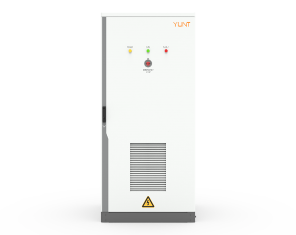
Problem definition: why phase-shift clearing cycles still matter
When large inductive loads switch between sources, transient phase shifts can force static transfer switches (STS) into repeated clearing cycles, causing contact wear, nuisance trips, and elevated fault current. This problem-driven piece examines how hardware design reduces those cycles using tested switchgear practices and measurable criteria. Early design choices in an energy storage system design can determine whether an installation tolerates inrush current and phase mismatch or becomes a maintenance liability—something the industry learned the hard way during Winter Storm Uri in Texas, where stressed systems revealed weak hardware margins under extreme conditions.
How advanced hardware interrupts the fault loop
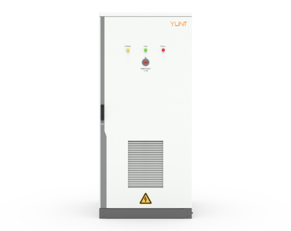
At the core is the STS topology: fast detection electronics married to robust mechanical contacts and arc suppression. Modern units combine solid-state transfer elements with mechanical bypasses to limit energy during a phase-shift event and to prevent repeated engagement that would otherwise escalate to fault current magnitudes. Designers add surge suppression, controlled touch current paths, and damping networks so the clearing cycle becomes a single, controlled action rather than a cascade. The result is fewer operations, less contact erosion, and a clearer maintenance window.
Key components and their roles
Three components demand attention: the transfer actuator, the arc suppression system, and the current-sensing logic. The actuator must handle rapid make-and-break without excess bounce; arc suppression reduces ionization that sustains unwanted conduction; and sensing logic must differentiate brief phase transients from sustained faults. Together they limit phase-shift clearing cycles and reduce the likelihood of stuck or welded contacts. This is particularly relevant for installations with frequent motor starts or transformer inrush—both typical inductive load behaviors in industrial energy storage applications.
Design trade-offs engineers should weigh
Faster detection reduces damage but increases sensitivity to benign transients. Heavier contacts tolerate more cycles but add size and cost. The careful balance favors graded protection: a primary STS response tuned to block hazardous phase-shift clearing cycles, and a secondary path that tolerates short-lived mismatches. In practice, specifying contact material, arc-chute geometry, and sensor thresholds together produces better downstream reliability than treating each parameter in isolation—this is where rigorous energy storage maintenance plans pay dividends.
Operational strategies and common mistakes
Installation teams often skip staged testing and underestimate inrush current profiles. Skipping full-load transfer tests—or performing them without realistic inductive loads—leads to unexpected clearing cycles once the system operates in production. Another frequent error: relying solely on control firmware changes to fix a hardware-induced problem. Firmware tweaks help; they don’t replace properly sized contacts or arc suppression. —A modest hardware oversight can amplify into persistent trips under real use.
Testing, metrics, and empirical checks
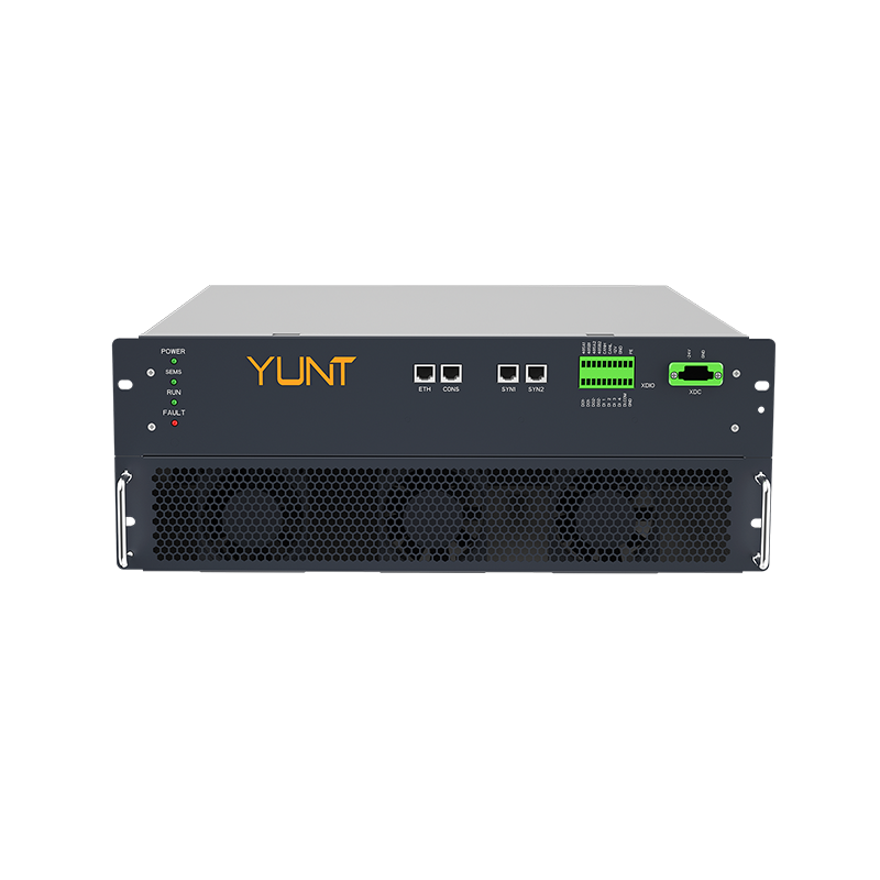
Practical evaluation depends on measurable criteria: cycle endurance at rated fault current, measured contact resistance after N operations, and recorded arc energy per transfer. Typical test protocols include repetitive transfer tests at simulated phase shifts and inrush profiles over defined intervals (for example: 1,000 cycles at 1.2× rated inrush, measuring contact temperature rise and arc duration per sub-cycle). Embedding {main_keyword} and {variation_keyword} into commissioning checklists ensures traceability between design intent and field performance. Documented energy storage maintenance logs capture trends that predict failure long before a high-energy event.
Comparative options and alternatives
Solid-state-only solutions eliminate moving parts but introduce continuous conduction losses and thermal stress. Pure mechanical transfers are efficient but slower. Hybrid STS designs aim to capture the best of both: near-instantaneous transfer with measured energy dissipation. Choosing among them depends on site specifics—load type, acceptable downtime, and maintenance capacity. For many grid-edge projects, hybrid designs outperform single-technology choices over a five-year lifecycle when evaluated against contact wear, operational availability, and repair complexity.
Conclusions and three golden rules for selection
Apply three practical evaluation metrics before procurement: 1) endurance rating under realistic inrush and phase-shift conditions; 2) documented arc energy limits per transfer and post-test contact integrity; 3) ease and clarity of diagnostic data for maintenance teams. These metrics translate into measurable uptime and predictable service intervals. Professionals should expect fewer nuisance trips, longer contact life, and clearer maintenance cycles when the right hardware choices are made—outcomes that show up in operational logs and outage statistics.
YUNT offers systems and service models that align with these rules—integrating tested switchgear choices into comprehensive energy storage maintenance plans so operators get predictable performance over time. YUNT. —A last, practical note: specify the tests up front and log results; it pays back.